- 您现在的位置:买卖IC网 > Sheet目录322 > DS2431GA+U (Maxim Integrated Products)IC EEPROM 1024BIT 2SFN
�� �
�
�DS2431�
�1024-Bit,� 1-Wire� EEPROM�
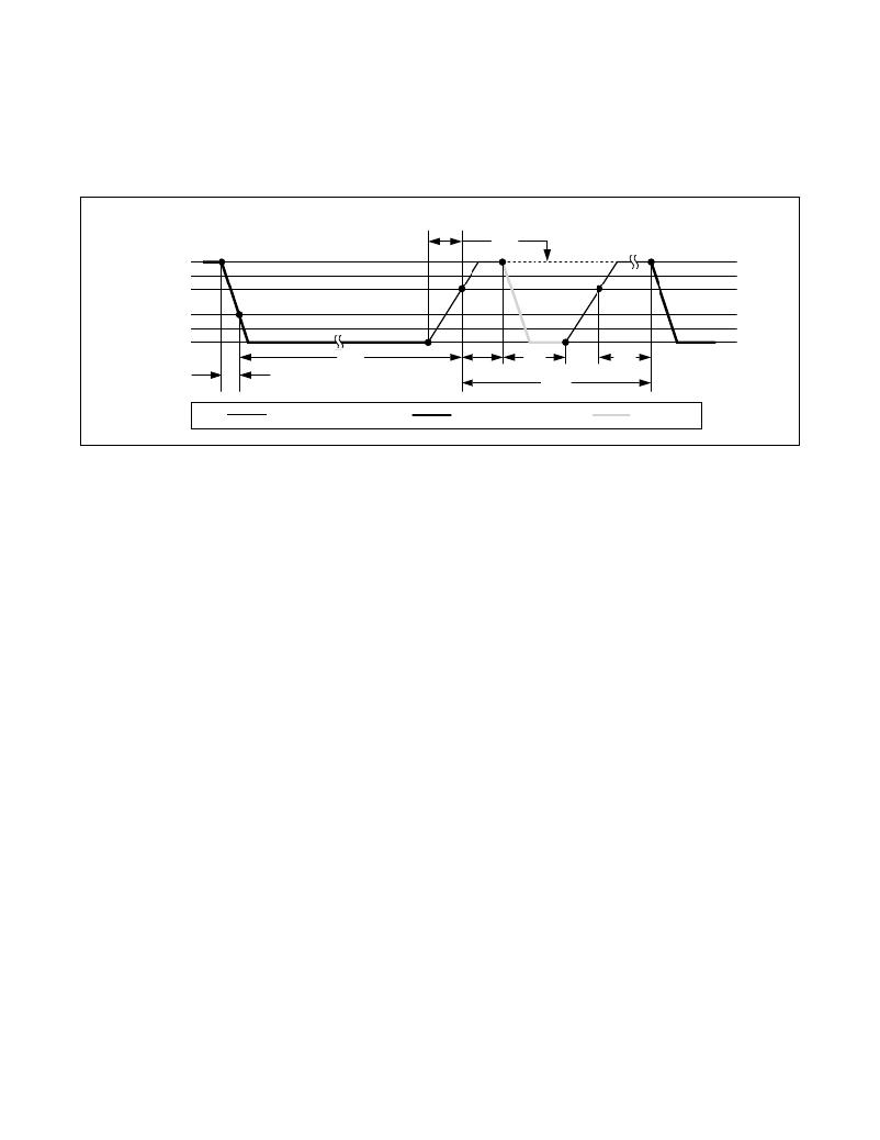
�V� PUP�
�V� IHMASTER�
�V� TH�
�V� TL�
�V� ILMAX�
�MASTER� Tx� "RESET� PULSE"�
�ε�
�t� MSP�
�MASTER� Rx� "PRESENCE� PULSE"�
�0V�
�t� RSTL�
�t� PDH�
�t� PDL�
�t� REC�
�t� F�
�t� RSTH�
�RESISTOR�
�Figure� 10.� Initialization� Procedure:� Reset� and� Presence� Pulse�
�MASTER�
�DS2431�
�Read/Write� Time� Slots�
�Data� communication� with� the� DS2431� takes� place� in�
�time� slots� that� carry� a� single� bit� each.� Write� time� slots�
�transport� data� from� bus� master� to� slave.� Read� time�
�slots� transfer� data� from� slave� to� master.� Figure� 11� illus-�
�trates� the� definitions� of� the� write� and� read� time� slots.�
�All� communication� begins� with� the� master� pulling� the�
�data� line� low.� As� the� voltage� on� the� 1-Wire� line� falls�
�below� the� threshold� V� TL� ,� the� DS2431� starts� its� internal�
�timing� generator� that� determines� when� the� data� line� is�
�sampled� during� a� write� time� slot� and� how� long� data� is�
�valid� during� a� read� time� slot.�
�Master-to-Slave�
�For� a� write-one� time� slot,� the� voltage� on� the� data� line�
�must� have� crossed� the� V� TH� threshold� before� the� write-�
�one� low� time� t� W1LMAX� is� expired.� For� a� write-zero� time�
�slot,� the� voltage� on� the� data� line� must� stay� below� the�
�V� TH� threshold� until� the� write-zero� low� time� t� W0LMIN� is�
�expired.� For� the� most� reliable� communication,� the� volt-�
�age� on� the� data� line� should� not� exceed� V� ILMAX� during�
�the� entire� t� W0L� or� t� W1L� window.� After� the� V� TH� threshold�
�has� been� crossed,� the� DS2431� needs� a� recovery� time�
�t� REC� before� it� is� ready� for� the� next� time� slot.�
�Maxim� Integrated�
�Slave-to-Master�
�A� read-data� time� slot� begins� like� a� write-one� time� slot.�
�The� voltage� on� the� data� line� must� remain� below� V� TL�
�until� the� read� low� time� t� RL� is� expired.� During� the� t� RL�
�window,� when� responding� with� a� 0,� the� DS2431� starts�
�pulling� the� data� line� low;� its� internal� timing� generator�
�determines� when� this� pulldown� ends� and� the� voltage�
�starts� rising� again.� When� responding� with� a� 1,� the�
�DS2431� does� not� hold� the� data� line� low� at� all,� and� the�
�voltage� starts� rising� as� soon� as� t� RL� is� over.�
�The� sum� of� t� RL� +� δ� (rise� time)� on� one� side� and� the� inter-�
�nal� timing� generator� of� the� DS2431� on� the� other� side�
�define� the� master� sampling� window� (t� MSRMIN� to�
�t� MSRMAX� ),� in� which� the� master� must� perform� a� read�
�from� the� data� line.� For� the� most� reliable� communication,�
�t� RL� should� be� as� short� as� permissible,� and� the� master�
�should� read� close� to� but� no� later� than� t� MSRMAX� .� After�
�reading� from� the� data� line,� the� master� must� wait� until�
�t� SLOT� is� expired.� This� guarantees� sufficient� recovery�
�time� t� REC� for� the� DS2431� to� get� ready� for� the� next� time�
�slot.� Note� that� t� REC� specified� herein� applies� only� to� a�
�single� DS2431� attached� to� a� 1-Wire� line.� For� multide-�
�vice� configurations,� t� REC� must� be� extended� to� accom-�
�modate� the� additional� 1-Wire� device� input� capacitance.�
�Alternatively,� an� interface� that� performs� active� pullup�
�during� the� 1-Wire� recovery� time� such� as� the� DS2482-�
�x00� or� DS2480B� 1-Wire� line� drivers� can� be� used.�
�17�
�发布紧急采购,3分钟左右您将得到回复。
相关PDF资料
DS2433X-S#T
IC EEPROM 4KBIT 6FCHIP
DS2433X-Z01
IC EEPROM 4KBIT 6FCHIP
DS24B33G+T&R
IC EEPROM 4KBIT 2SFN
DS2502-E64+
IC OTP 1KBIT TO92-3
DS2502P-E48+T&R
IC OTP 1KBIT 6TSOC
DS2502S+
IC OTP 1KBIT 8SOIC
DS2505+T&R
IC OTP 16KBIT TO92-3
DS25LV02R+T&R
IC OTP 1KBIT SOT23-5
相关代理商/技术参数
DS2431G-W0V+2T
制造商:Maxim Integrated Products 功能描述:1024-BIT 1-WIRE EEPROM - Tape and Reel
DS2431G-W0V+3T
制造商:Maxim Integrated Products 功能描述:1024-BIT 1-WIRE EEPROM - Tape and Reel
DS2431G-W0V-2T
制造商:Maxim Integrated Products 功能描述:
DS2431G-W0V-3T
制造商:Maxim Integrated Products 功能描述:
DS2431P
功能描述:电可擦除可编程只读存储器
RoHS:否 制造商:Atmel 存储容量:2 Kbit 组织:256 B x 8 数据保留:100 yr 最大时钟频率:1000 KHz 最大工作电流:6 uA 工作电源电压:1.7 V to 5.5 V 最大工作温度:+ 85 C 安装风格:SMD/SMT 封装 / 箱体:SOIC-8
DS2431P R
制造商:MAXIM 制造商全称:Maxim Integrated Products 功能描述:1024-Bit, 1-Wire EEPROM
DS2431P T
制造商:MAXIM 制造商全称:Maxim Integrated Products 功能描述:1024-Bit, 1-Wire EEPROM
DS2431P/R
制造商:DALLAS 制造商全称:Dallas Semiconductor 功能描述:1024-Bit 1-Wire EEPROM